Infrared Camera Description
Dewar
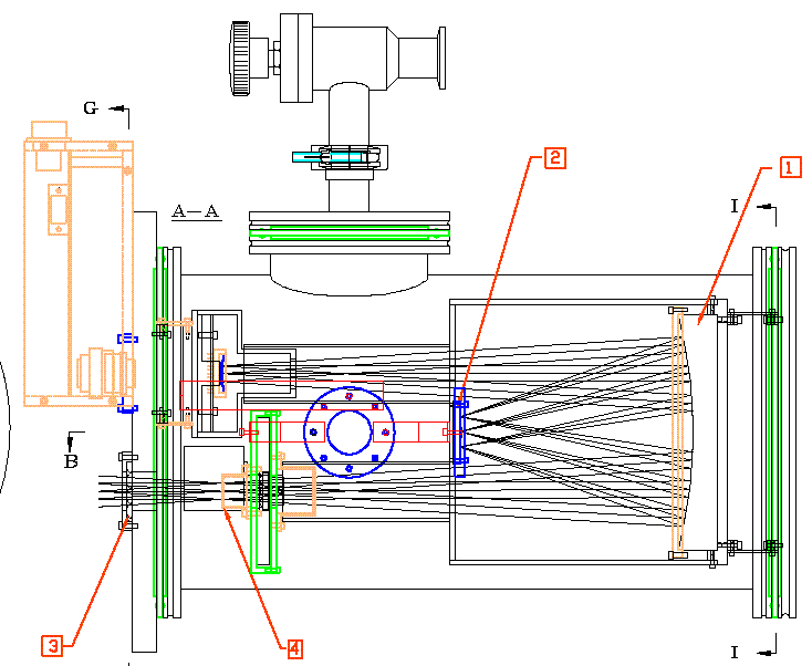
The chip is mounted in a vacuum Dewar with cooled re-imaging optics.
The Mark II version of the camera uses a cooled Offner relay
system to reimage the focal plane onto the detector.
This system has an intermediate pupil (image
of the telescope primary), that is cooled and so
the field of view looking out of from the chip will
be tightly controlled to only see the telescope mirrors
and the sky beyond. All other rays will strike cooled surfaces that
emit
little thermal background radiation.

The filters
are mounted in rotatable filter
wheel and are cooled to reduce thermal background. A stepper motor
rotates the wheel.
An LED and photosensor establish the home position.
There are four AD590
temperature sensors mounted in the Dewar.
One is on the 77K cooling station and measures the
main cooling temperature.
A second one is on the radiation shield of the optics.
The third one is mounted on the filter wheel case.
The fourth is on the chip mount. All temperatures are reported in
Kelvin.
Detector
The camera uses the
Rockwell Picnic Array with the following properties.
- HgCdTe detector
- 256x256 pixels
- 40 micron pixels
- 250,000 electron full well
- 100 electron readout noise
- 77K nominal operation temperature
The detector is composed of two parts: a thin substrate of HgCdTe
(pronounced Mer-kad Tel) which is aborbs the infrared light
and generates electrons and a
silicon multiplexer which contains the complex switching array which
routes the charge from the pixels to one of four on board output
amplifiers.
Controller
The camera is controlled by several commercially available cards in an
IBM PC clone.
A level shifter, interconnect box is mounted on the vacuum Dewar.
A diagram of the system is shown in ircam001
drawing.
The clock sequences needed by the camera are generated by
a PCIP-AWFG
arbitrary waveform generator card made by the Keithley Instruments.
It has can generate 8 different TTL compatible clock levels with
a maximum pattern length of 32K.
They are converted to 0-5 volts clocks by a High Speed CMOS
chip.
The four outputs of the detector pass through amplifiers with
a gain of (X5.1) and a manually adjustable offset to a 16 bit analog
to digital converter card model DAS1602/16
made by Computerboards.
It has a 10 microsecond conversion time so the entire
chip can be read in 0.65 second.
The data from this card pass through a very large FIFO (Mega Fifo by
Computerboards)
so that
they do not have to be read in real time.
Readout
The chip is readout by clocking the multiplexer so
that each picture element (pixel) is sequentially connected
to one of the four output amplifiers.
When the pixel is accessed the charge is measured but not
removed. This behavior is different from that used CCD (Charge Couple
Device)
detectors in which the process of reading the chip by its nature resets
the pixels.
Instead a separate command is needed to reset the pixel and clear
the built up charge.
Additionally the charge can be read many times in order to get
a more accurate measurement (decrease the readout noise).
Since the camera does not have a mechanical shutter, timed exposures
are made by resetting the chip, waiting for the desired exposure time,
then reading the chip again.
While the chip is not being read out it is constantly clocked with
a reset waveform to flush out the building up charge.
The waveform generation is discussed in more detail here.
Our camera has several ways in which it
can be readout out.
Note:: in the following the term expose
means wait the requested duration.
- Fowler - resets, read, expose, read - the default
- Frame- reset, expose , read
- Reset- resets the chip but does not read it
- CDS - resets&read, expose, read
- Read - reads chip but doesn't reset.
When a sequence involves two reads the difference of the second - first
read is returned. This usually leads to a positive value of the signal.
To select these we have added a subcommand to the ccd_status
command can be used to select the
sequencer by specifying its name in the seq field.
For example:
tx ccd_status seq=Fowler
Cooler
The chip is cooled using a Model 21 closed cycle helium
refrigerator made by
CTI Corp.
Specific information for our refrigerator unit is found here. The high pressure gas is supplied by a
compressor mounted
downstairs manufactured by Austin
Scientific.
Thermal Design
Below is a work sheet for the redesigned IR camera so that
the thermal backgrounds will be small in comparison to
the sky the signal.
First we need to know how cool the inner box surrounding the
detector.
Last updated on 2000 November 21

